
Thoughts about software engineering, and game development.
TopicsSoftware DevelopmentGeometryProcedural content generationSoftware SecurityMeta |
1. Smooth collisions part 2 : AABB versus segment, solving the issue of "internal edges"TL,DR: use thick segments with rounded vertices. TL,DR: The full code is at https://github.com/Ace17/collide2d and is less than 200 lines (+ an extra interactive SDL app). 
(I’m assuming you’ve already read "Smooth collisions part1") Today, if you’re implementing a 2D game, you have two choices:
All the 2D console games from the 16-bit era went with 2). But they feature carefully crafted levels, designed around the limitations of their ad-hoc physics engines. For example, you might need to avoid "pointy" platforms, or ground discontinuities next to sloped ground. Some passages of Super Mario Bros 3 actually rely on the specific way the game resolves collisions "to the right". It turns out that even for a game seemingly simple like Super Mario Bros, properly implementing game-specific physics is hard. I’m not talking about a game that feels right, I’m talking about basic stuff, like non-penetration constraints and smooth wall/slope sliding. Basic tile-based collision detection and response are actually pretty easy ; When it comes to implementing slopes or moving platforms, this becomes more complicated. This might explain why 1) seems to be quite popular today, although it certainly brings new issues (see https://web.archive.org/web/20160304043558/http://www.learn-cocos2d.com/2013/08/physics-engine-platformer-terrible-idea/ ). There are tricks to avoid most of these issues. In the previous post, we saw how to implement basic ad-hoc disk/segment collisions. Now we see how to implement AABB/segment collisions. This is trickier than it seems. Colliding a disk is easy, because a disk is basically a thick point. Which means, there’s no need to use a dedicated representation for the contour (like with polygons). Given a point inside a disk, it’s obvious in what direction we should push it out, and computing penetration depth is straightforward. And, most importantly, the contour of a disk doesn’t have corners, so we can always use it to compute a realistic collision normal. Physics engines like Box2D are able to handle many kind of shapes. Especially, boxes, which you can’t really avoid if you’re making a 2D platformer. In Box2D, there’s one issue that’s not been taken care in a satisfying way: the issue of internal edges, also known as "inner corners", "sticky corners", or "internal vertices". Actually, this isn’t really specific to the way Box2D is implemented: this is a more fundamental issue that needs special handling. This issue is described in detail here: https://wildbunny.co.uk/blog/2012/10/31/2d-polygonal-collision-detection-and-internal-edges/ But I’m going to give a simplified explanation below. Then, we will implement basic box / segment collisions, and see the problem happen with our implementation. Then, we will make an attempt at solving it … and hopefully, succeed :-) 1.1. The problem with internal edgesSuppose the main character is an AABB ( axis-aligned bounding box ), and it’s walking on a bridge composed of two solid, vertically-aligned bricks, each one also an AABB. To the eyes of the player, the ground of the bridge is continuous ; however, from the physics engine point of view, both bricks are independent, and must be tested for collisions separately. 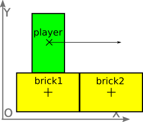
This leads to issues when transitioning between the two bricks, like the main character getting stuck in the middle of the bridge. This happens because the bottom right corner of the main character collides against the left side of brick2, leading to a collision response that pushes the main character to the left. 1.1.1. The X/Y workaroundIf your game is only composed of perfectly-grid-aligned collidable tiles, you might save yourself some trouble by applying the following trick:
This technique is fully described here: http://higherorderfun.com/blog/2012/05/20/the-guide-to-implementing-2d-platformers/ However, this technique relies on giving the X/Y axes very specific roles, and assumes that almost all your walls are horizontal or vertical. The usage of slopes in this context requires special handling, and is rather constrained. If you’re making a top-down shooter and your level geometry is made of arbitrary polygons, you’re out of luck. 1.2. Collisions in one dimensionWe’re going to start with the simplest case: collision detection in one dimension! On the below diagram, we’re colliding the range A with the range B. (I’m avoiding here the word "segment", because I want to avoid confusion with 2D segments, i.e our walls). In every case, we suppose A is the moving object, while B stays static. Our goal here is to detect the collision between A and B, if any. In this case, we also want to compute the collision normal and the penetration depth. The collision normal will tell the collision resolver in which direction should A be moved (left or right), and the penetration depth will tell by how much. 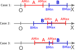
Case 1 is the simplest: we have AMax < BMin, so there can be no collision. By symmetry, there’s also no collision if BMax < AMin. In Case 2, A and B collide. We want to move A slightly to the right, so it doesn’t collide anymore. However, we could also resolve the collision by moving A to the left. This would require a bigger move, though. In Case 3, A and B still collide, but this time, A is more "on the left" of B. We could favor the direction which minimizes the length of the corrective move. However, to keep things simple, we’re going to use a cheap heuristic. struct Range { float min, max; }; struct RangeCollision { float depth; // penetration depth float normal; // 0 for no collision, -1 for left and +1 for right }; RangeCollision collideRanges(Range a, Range b) { if(a.min > b.max) return RangeCollision{0, 0}; // case 1, with 'a' 'on the right' of 'b' if(a.max < b.min) return RangeCollision{0, 0}; // case 1, with 'a' 'on the left' of 'b' auto const centerOfA = (a.min+a.max)*0.5; auto const centerOfB = (b.min+b.max)*0.5; if(centerOfA < centerOfB) return RangeCollision{a.max - b.min, -1}; // the left of 'a' is still outside 'b': push left else return RangeCollision{b.max - a.min, 1}; // otherwise, push right } I must admit that collisions in 1D aren’t very interesting, so let’s move on! 1.3. Collision of convex shapesDetecting collisions between two convex shapes relies on the following fact: If one point of view exist, from which you can take a photo showing that both shapes don’t collide, then they don’t collide. If no such point of view exist, they collide. For example, to tell if two cars in a line touch, the point of view would be from the side. From the back, you wouldn’t be able to tell. Remember, the shapes must be convex. For example, there’s no point of view from which you can separate two entangled rings, although they still might not touch. This is called the separating axis theorem, aka "SAT". This is how many first-person shooters actually work (e.g the Quake series and all its derivatives). Now, for a more "mathematical" formulation of the SAT. You have two objects A and B, and an infinite line S (as in "separator"). Let’s call range A' and range B' the orthogonal projections of A and B on S. Depending on how you choose S, there might be an overlap between A' and B', or not. If some S exists so that A' and B' don’t overlap, then S is an axis that "separates" A and B. In one word, S is the proof that A and B don’t collide. But what if you can’t find such an S? Does it mean that A and B necessarily collide? Yes, but only if A and B are both convex. Otherwise, we cannot tell. 1.4. The penetration depthBut we don’t simply want a boolean answer to our collision test ; we also want to measure the penetration depth. Let’s suppose now that A and B don’t actually collide, but you’re trying a "bad" separating axis S. There’s some non-zero amount of overlap between A' and B', which is our penetration depth, measured from the point of view of this specific candidate axis. The "real" penetration depth is the minimum (potentially negative) amount of overlap between A' and B', for all axes. So now, if you slightly rotate S around the origin, the amount of overlap will change, and eventually become negative, when the direction of the axis will actually be a separator. So the workflow is simple: test all axes, and keep the one that gives the smallest (i.e most negative) penetration depth. 1.5. Which axes should we test?If you’re working with polygons, in theory, choosing S is simple: S is always orthogonal to one of your segments. So if you’re working only with AABB, your segments are always horizontal or vertical. This means you only have two candidates to test to find S:
Here we want to stay generic, because we’re going to add more axes later. So, we will use a list of axes to test, and treat each of them in a generic way. When possible, I avoid dealing directly with coordinates. I prefer a more geometrical approach, based on vectors and scalar products. I find it easier to visualize, and it makes a potential switch from 2D to 3D easier. 1.6. How to project the objects on an arbitrary line?Say you have a line S. Without loss of generality, we can assume that S passes through O, the origin of the reference frame. N is the normalized tangent vector of S. We will use the multiplication sign "*" to denote the scalar product. 1.6.1. Projecting a diskLet’s now consider the yellow disk below. We can represent its projection on S using two scalars: diskMin and diskMax. This is what I call the projection "range" of the disk on S. Computing the disk range is straightforward: auto diskMin = C * N - radius; auto diskMax = C * N + radius; 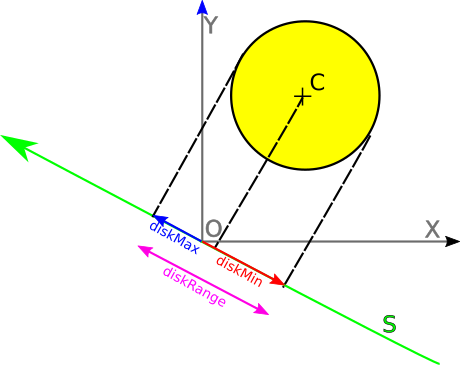
1.6.2. Projecting an AABBThis is actually what we’re going to use for our collisions. Let’s consider the yellow box below:
Computing the box range requires to compute a … radius for a box. It turns out this makes perfect sense: it’s the radius of a disk that would have had the same projection range. It can be computed using the below formula. (This formula can be derived by projecting all box corners, and taking the max and min values). auto radius = abs(N.x * boxHalfSize.x) + abs(N.y * boxHalfSize.y); auto boxMin = C * N - radius; auto boxMax = C * N + radius; 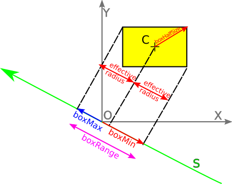
1.6.3. Projecting a segmentFor segments, this is even simpler. Let’s now consider the yellow segment below:
auto segMin = min(a * N, b * N); auto segMax = max(a * N, b * N); 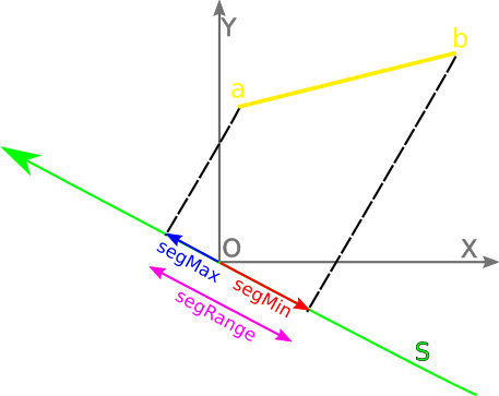
Please note that if S is orthogonal to the segment, then segMin = segMax. 2. Implementing SAT: a first attemptSo now, we’re ready to implement a first version of the SAT algorithm. This will collide an AABB against a segment. This version will be inefficient, but simple and - hopefully - correct! Here we’re testing 3 axes: * the X and Y axes (because they’re orthogonal to the AABB edges). * the axis that is orthogonal to the segment: to get it, we rotate 90 degrees a normalized tangent. Range projectBoxOnAxis(Vec2 boxCenter, Vec2 boxHalfSize, Vec2 N) { auto boxEffectiveRadius = abs(boxHalfSize.x * N.x) + abs(boxHalfSize.y * N.y); auto boxPos = boxCenter * N; auto boxMin = boxPos - boxEffectiveRadius; auto boxMax = boxPos + boxEffectiveRadius; return Range { boxMin, boxMax }; } Range projectSegmentOnAxis(Segment seg, Vec2 N) { auto segMin = min(seg.a * N, seg.b * N); auto segMax = max(seg.a * N, seg.b * N); return Range { segMin, segMax }; } static Collision collideBoxWithSegment(Vec2 boxCenter, Segment seg) { auto const boxHalfSize = Vec2(RAY, RAY); Vec2 axesToTest[] = { Vec2(1, 0), // X axis Vec2(0, 1), // Y axis rotateLeft(normalize(seg.b - seg.a)), // segment normal }; Collision r = { INFINITY, Vec2(0, 0) }; for(auto N : axesToTest) { auto rangeOfA = projectBoxOnAxis(boxCenter, boxHalfSize, N); auto rangeOfB = projectSegmentOnAxis(seg, N); auto collision = collideRanges(rangeOfA, rangeOfB); // keep the smallest measured depth (potentially zero if no collision) if(collision.depth < r.depth) { r.depth = collision.depth; r.N = N * collision.normal; } } return r; } If you try this code, it will appear to work. However, here’s the catch: 
Do you see how the AABB sometimes get stuck when passing on the extra vertex? There you have it: the infamous issue of internal edges! This behavior is certainly not easy to trigger, but it’s definitely there. How to get rid of it? 3. Why does it occur?What are we missing here? And why does this phenomenon occur anyway? It has to do with the choice of the collision normal. If the AABB stops moving, it’s because something is blocking it, which means we’re getting an unexpected collision normal. In the case from the animated GIF above, we’re getting the following normals:
Why are we getting this left-pointing normal? And why are we getting two different normals anyway? Because, both are valid separating axes, according to our selection criteria : they both minimize the penetration depth. This ambiguity arises because the corner of our bounding box touches the leftmost corner of the small triangle. We could try to enhance our separating axis selection criteria. Or better, we could reshape the world in order to avoid such discontinuities of the collision normal. It’s easy to conceive that the sliding motion can’t be smooth if the collision normal is discontinuous relative to the box position. 4. Just make them thickSo here comes the trick: let’s disallow infinitely small "pointy" corners altogether. Let’s make them "thick" vertices (think: disks), and while we’re at it, let’s also have "thick" segments (having only one of both is a recipe for more trouble!). Here’s what I mean: 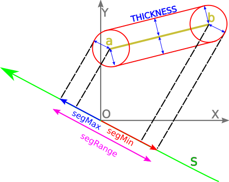
The area delimited by the red frontier represents the "forbidden area". If something penetrates here, it’s colliding, whether it touches the original yellow segment or not. And now, here’s a zoom on the problematic segments from the above animated GIF, but with thick segments: 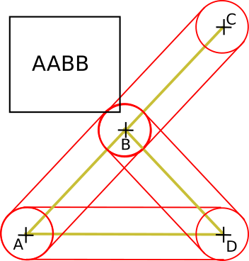
5. Implementing SAT: an smooth enhancementWe must first choose an arbitrary thickness value: I suggest to use the greatest visually acceptable value. Here, I choose 0.1. Having thick-rounded segments has two consequences. The first consequence is that we need to slightly modify the projectSegmentOnAxis method. We now need to take the thickness into account. No big deal here, at this point, we’re already projection wizards. Range projectSegmentOnAxis(Segment seg, Vec2 N) { const float THICKNESS = 0.1; auto segMin = min(seg.a * N, seg.b * N) - THICKNESS; auto segMax = max(seg.a * N, seg.b * N) + THICKNESS; return Range { segMin, segMax }; } If you launch the code with this modification only, you will notice that the issue of internal edges just got worse! Indeed, this is because the "best" separating axis isn’t in our list anymore. This is the second consequence: by rounding everything, we just made the candidate list of separating axes infinite again. Fortunately, we can use a trick here. At this point, we don’t need infinite accuracy, we just want something to prevent our AABB from getting stuck. So we just add the following axes to the list of candidate axes:
  Vec2 axesToTest[] =
  {
     Vec2(1, 0), // X axis
     Vec2(0, 1), // Y axis
     rotateLeft(normalize(seg.b - seg.a)), // segment normal
     normalize(center - seg.a),
     normalize(center - seg.b),
  };
}
6. ConclusionThis is it! No more getting stuck into ghost corners. Now, you don’t have anymore excuses for not working on your killer 2D game! What we did here was to give to a precision threshold (THICKNESS) a first-class geometrical interpretation. Simply adding 0.1 to segments' projected ranges, while seemingly a good idea, actually worsened the issue ; because we also needed the extra candidate axes. But to see this, this threshold had to have some geometrical meaning. The full source code is available here: Of course, this code is far from being efficient, there’s room for many optimizations. By exiting early, we could avoid lots of computations, especially the normalizations, which involve costly calls to sqrt. For educational reasons, I’ll be keeping the code on github as small as possible. Pull requests to improve readability or compactness are welcome ; if you want to suggest optimizations, I’ll happily create a "fast" version of the code, and maintain both versions. As the old man say: first, make it numerically robust; then, make it fast! |